Safe implementation of collaborative robot applications
Safe implementation of collaborative robot applications
The word ‘cobot’ has been an integral part of automation concepts in large, medium and small enterprises in all industries for several years now. Nevertheless, there are very often gaps in knowledge and misunderstandings in this area when it comes to the handling, characteristics and possibilities of this technology. The intention of this blog post is to help users of this technology to get a better understanding of the world of collaborative robotics and will hopefully help to get more safe implementations of fenceless robot applications.
The word cobot
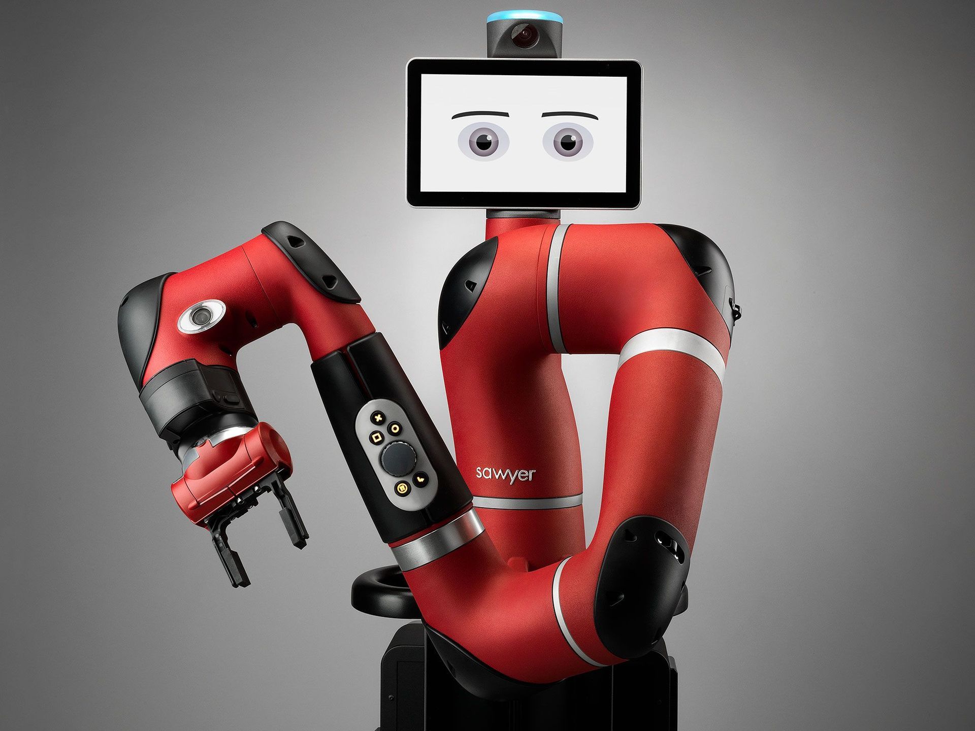
In one of our previous blog posts, which you will find, following this link, we already dealt with the term ‘cobot’. We already pointed out that this term is misleading, as it implies that the robot itself is always safe. But the fact is, even the most sensitive robot with a knife in its gripper can cause serious injuries. The collaborative robot itself therefore does not exist, only collaborative robot applications, and whether these are actually safe must be clarified as part of a risk assessment. You can also find an informative blog post on the topic of risk assessment here.
Types of collaborative applications
EN ISO 10218-1/-2:2011 currently specifies four different types of collaboration. These are in particular
- Safety rated monitored stop (e.g. applications in which a laser scanner brings the robot to a safe standstill when a person enteres the robot working area)
- Handguided control (with direct control of the robot at the end effector, e.g. by means of a force/torque sensor. A three-position enabling device on the end effector is also reuired in these kind of applications)
- Speed and seperation monitoring (the robot slows down the closer a person gets to the robot)
- Power and Force limiting (the robot recognises an unintended collision and stops without injuring the person)
However, the new ISO 10218-1/-2 (to be published in 12/2024) no longer includes these types of collaboration. Ultimately, the new standard only defines, what is meant by collaboration. It is important to note that there is NO definition of a collaborative robot in this new standards, only the definition of a collaborative robot application.
According to this standard, a collaborative robot application is an application that contains one or more collaborative tasks. A collaborative task is defined as follows:
‘Part of the robot sequence where both the robot application and the operator(s) are in the same safeguarded space’
This means, if an operator or a person is able to enter into the robot's workspace, either completely or with parts of his body, while the robot is operating in this space, it is defined as a collaborative application. In most cases, this will be achieved by using the above mentioned method of power and force limiting. But how could such an application be implemented safely?
In this blog post, we deliberately do not want to go into the evaluation of an application as part of a subsequent force and pressure measurement, as this would go beyond the scope of a blog post. Instead, we would like to give you a few recommendations on what you should keep in mind when implementing a collaborative robot application.
Consult experts
First of all, it is ultimately up to you to decide whether you are confident enough to implement such an application safely on your own and also prepare the associated risk assessment at the end by yourself. However, if you are considering having the risk assessment carried out by external experts, such as e.g, our company Cobot Safety, then do yourself and us a favour - please don't wait until the end of your project to call in external expertise. We at Cobot Safety, as well as our competitors, don't like to be the spoilsport who tells you in the end that the application is quite nice, but ultimately will not receive a positive risk assessment and therefore no declaration of conformity in accordance with the EG Machinery Directive. The costs of changes to implement safety concepts that will achive a positive risk assesment will be much higher, if you do your changes in the end of the process. Safe your money and get your external experts on board as early as possible. We and our competitors in the field of risk assessments generally welcome, if customers contact us with a concept idea and we will have the possibility to advise you in an early stage of your project.
The most sensitive topic - the head area
When it comes to collaborative robot applications, everyone has certainly heard or allready had the discussion about the head area. You may often heared that collisions with the head area are prohibited and that a safe application without a safety fence is only possible if a collision with the head can be completely ruled out.
However, the problem about this topic is usually that you can restrict and control the movements of the robot in principle. This might prevent that the robot is moving into the head area of the employee. But what's may not really under our controll is the movement of the employee. In an fenceless application, you can therefore never 100% rule out the possibility of the employee moving his head into the robot's working area. So if a collision with the head were prohibited in any case, this will cause, that all collaborative robot applications would fail.
The opinion that collisions with the head area are not permitted is mainly based on an incorrect interpretation of the ISO/TS 15066. Here you will find a table with biomechanical limit values in Annex A, which shows the following entry for the head area:
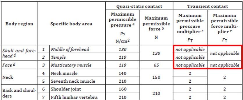
Figure 1: Extract from Table A.2 of ISO/TS 15066
In the table shown above, ‘Not applicable’ is indicated in the transient contact column for the head region, while a value can be found in the quasi-static contact area. However, it is important to note that ‘not applicable’ does not mean ‘prohibited’. It means that no value are available in this informative list of biomechanical limits, because no value has been determined or could be determined for this body region. A collision with the head region is therefore not absolutely impermissible. There are just no reference values to determine, as part of the risk assessment, when a collision is critical and when it is still uncritical . Therefore, the assessment of collisions in the head area will depend subjectively on the assessor himself.
Nevertheless, collisions with the head area should always be excluded as far as possible. As a first step, this will start with the mounting height and the working height of the robot. You should always try to mount the robot base as low as possible in order to keep as many robot movements as possible below a height of 1.5 metres, as long only male employees have access to the robot's working area. If women are also working in the robot's area, a maximum working height of 1.3 metres is recommended. Almost all manufacturers of ‘cobots’ offer an option of restricting the robot's working area using safety functions. Figure 2 shows an application with a UR10e in which it uses the gripper (circled in red) to remove a stack of paper from a machine at the point labelled with 1 and places it on the pallet (labelled 2). As the robot does not have to travel higher than the safety level shown in red during normal use, this safety plane can be used to prevent the robot from travelling into the head area due to a programming error or improper reprogramming.
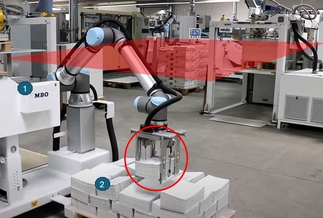
Figure 2: Use of a safety level on a UR10e
However, Figure 2 raises two further issues that need to be considered, even if these do not relate exclusively to the head area.
- Gripper design: Particularly when it comes to collaborative applications, the integrator should pay a lot of attention to the geometry of your gripper. Sharp edges, small surfaces, hard metal, etc. should be avoided wherever possible. Figure 3 compares a positive and negative example using a vacuum gripper. In the application shown in Figure 2, there is certainly still some potential for improvement in the gripper area.
- Speed:
The speed of the robot at the moment of collision in particular is one of the main factors on how severe an injury can be in the event of a collision. Therefore, movements in the head area should be carried out at a slow speed if they cannot be completely ruled out. However, it is not sufficient to reduce the speed in the programme, as this can theoretically be increased again at any time by someone with access to the programme code. An error in the non-safe part of the control system can also cause the robot to move faster than programmed. Only limiting the speed in the safety system can have a positive influence on the outcome of the risk assessment.
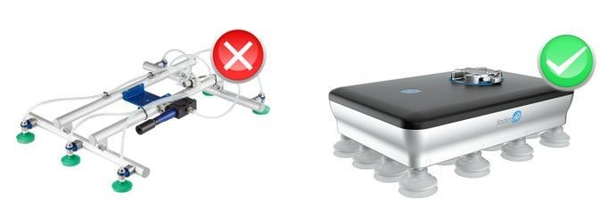
Figure 3: Positive and negative example of a collaborative gripper design
If you have taken these points into account so far, you have already done a lot of things right. However, there is of course still the problem of employees sticking their heads into an area where they have no business being. Sp let's see if there is still room for further optimisation.
Figure 4 shows an application in which filters are removed from a box, will be geripped in a geripping station, placed in a machine, checked inside of the machinery, removed out of the machine and placed on a storage area. The head area was also rated as critical in this application. For this reason, the application was partially fenced. Access on the left-hand side is only possible by opening the door. In this area, the robot moves into the head area on the one hand, and on the other hand a possible crushing at the handling station was critical. So opening the door on the left will now cause the robot will entering a safety rated monitored stop. On the front and right, the fencing is only in the upper area. Reaching into the pick-up and placing area with the hand and forearm is possible without any problems. This is safeguarded by the power and force limiting of the robot control system. A collision with hands, fingers and forearms will be below the biomechanical limit values of ISO/TS 15066 (This is approved by a presure and force measurement). The probability of the employee sticking his head into the robot's working area has been significantly reduced with this measure and ensures that the risk is within an acceptable range.
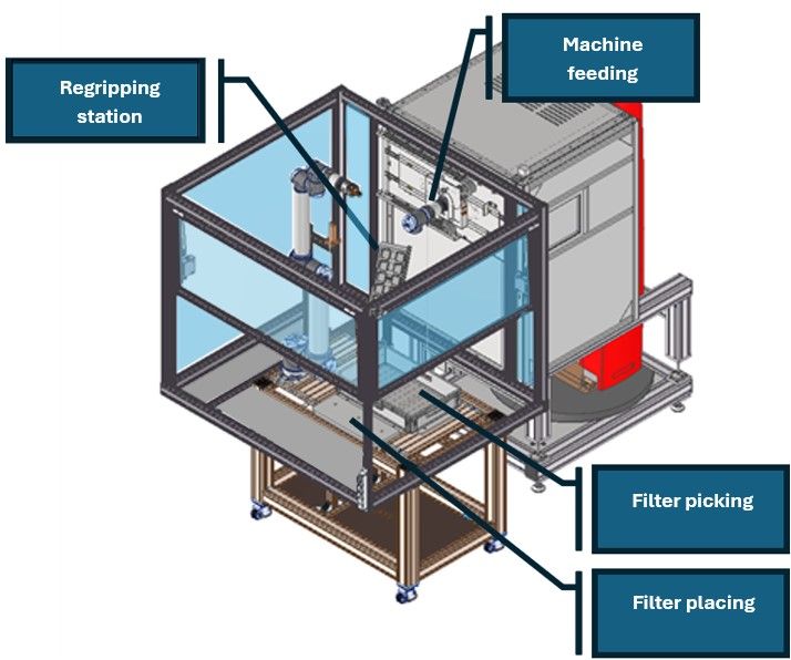
Figure 4: Example of a partial enclosure to exclude the head area
If you have considered all of these points in your planning and concept phase, you are already on the right track and have taken the most critical things, that may can affect the outcome of a risk assesment negeativly, into account.
Reducing potential pinch points
When assessing the safety of a collaborative robot application with power and force limiting, three mechanical hazards allways have to be considered. This three hazards are listed below from most critical to least critical:
- shearing
- crushing
- impact
These three mechanical hazards mentioned in the EG Machinery Directive can occur at various points in all collaborative applications. Some of them can be eliminated and removed and some remain and must then be assessed as part of a force and pressure measurement.
Figure 5 illustrates these three different hazards once again to show why clamping is more critical than impact and shearing is more critical than clamping.

Figure 5: Shearing vs. clamping vs. impact
The aim of minimising pinch and shear points should already be declared in the planning and concept phase. Where ever possible an application should be planned at a location where no obstacles are in the robot working area, so that it can move freely throughout the entire work area. Walls, support pillars, machines, etc. that are in the robot's working area will all cause potential shearing and clamping points. Of course, often it will not be possible to get all hazardous points away. Sometimes there is only room for the robot in one place. And this is where possible pinch and shear points exist.
Therefore, if you have not already been able to eliminate these hazards in the planning and concept phase, try to eliminate them in the development phase by using software limitations. Utilise the options for restricting the work space of your robot in terms of safety. All so-called cobots have a safety function for axis limitations and almost all of them also have a safety function for Cartesian space limitation. Some by means of planes, some by means of rooms or areas. Use this kind of safety functions to exclude areas of the robots workspace to minimize the robot working area to a minimum that is needed for its process. This will reduce the risk of shearing and clamping in an safety rated way. In a best case the only remaining crushing and shearing hazards are at point, that are needed for the process (e.g. picking and placing point). At this remaining points a force and presure measuring have to be done, to verify, that a possible collision will not cause any injury.
In an upcomming blog post, we will have a deeper look at the force and pressure measurement and also the evaluation and interpretation of the results. However, if you have followed this guidelines so far and have already eliminated as many pinch and shear points from your application you removed many of the potential stumbling blocks for the successful completion of your risk assessment and are well prepared for the way to successfully completing your cobot project.


